This is a proof of concept which uses an array of LDRs (Light Dependent Resistors) with RGB LEDs to scan and digitally reconstruct a color image. This was designed to scan a color image on A4-sized paper. The final resolution of the scanned image is 40x57 pixels.
At the heart of the scanner is an Arduino Nano board. Using five 8-channel analog multiplexers (74HC4051), the Arduino was able to read analog values of an array of 40 LDR. And it also has 12 RGB LEDs (WS2812B).
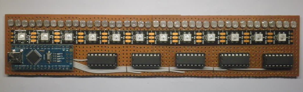 Prototype board of the LDR Scanner
To scan an image, the LDR array needs to move across the paper. For that, a rig was constructed using some pipes and the scanner was driven on top of it using a stepper motor and a belt.
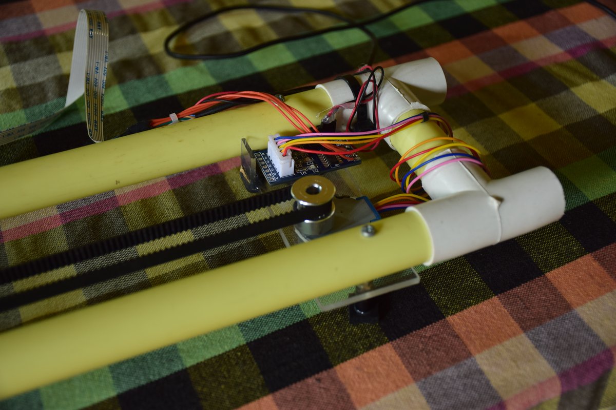 Stepper motor is used to move the scanner on the rig
The LDR produces a resistance value based on the amount of light it receives. By connecting an LDR with another resistor in a voltage divider configuration, we can build a crude light detector.
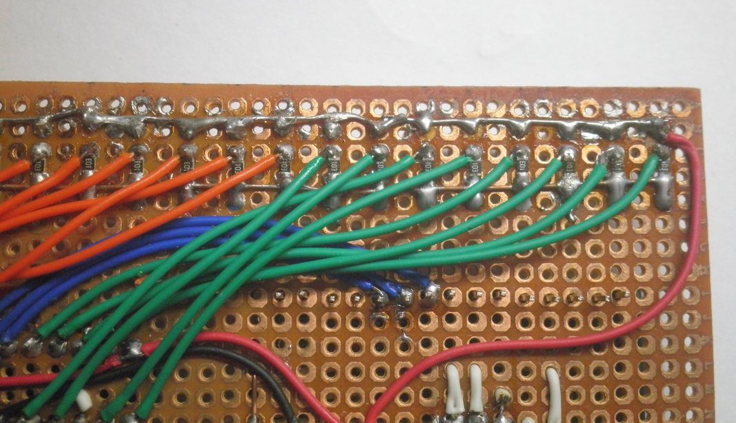 LDRs used in voltage divider configuration
When a white light incident on a surface, the surface will absorb some wavelengths of light and reflect the rest. What we perceive as the color of the surface is the color of the reflected light. We know that white light is made up of Red, Green, and Blue primary colors.
When these three colors were incident on a surface separately, we can get three different resistance values from the LDR for the reflected light. These reflected light intensities depend on the absorption of these three primary colors from the incident surface.
If we know what are the voltage values we get from LDRs when we shine these primary colors onto white and black surfaces, we can use that to calibrate our LDR color sensor. The sensor array was needed to be built in a way such that the LDRs should only expose to the reflected light from the surface. But completely eliminating the environmental light was not feasible for this prototype. Hence, the sensor calibration had to be done before every scan.
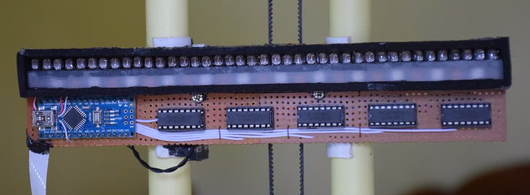 Scanner platform on the rig
Working of the scanner
In the beginning, the scanner moves to the right to its home position. After the scanner hits the limit switch at the home position the scanning process begins. The scanner illuminates the surface with red, green, and blue light in each step while saving the LDR readings.
Scanned images
These are some of the scans I got from this prototype. On the left, you can see the original image. And on the right side, you can see the scanned output of the scanner.
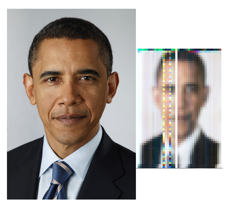 Original color image is on the left and scanned output is on the right
 Original color image is on the left and a partially scanned output is on the right
Source Files
You can find the source code of this project on my GitHub repository: LDR-Color-Scanner