The easiest way to apply solder paste onto a PCB is by using a stencil. But when prototyping, the layout of the PCB changes over time. For small PCBs often the stencil is more expensive than the PCB itself. So, using stencils for every board iteration is not very cost-effective. That is where solder paste dispensers come in.
There are two types of dispensers, not very DIY-friendly pneumatic ones and motor-controlled dispensers. In this project, I designed a motorized mechanical paste dispenser.
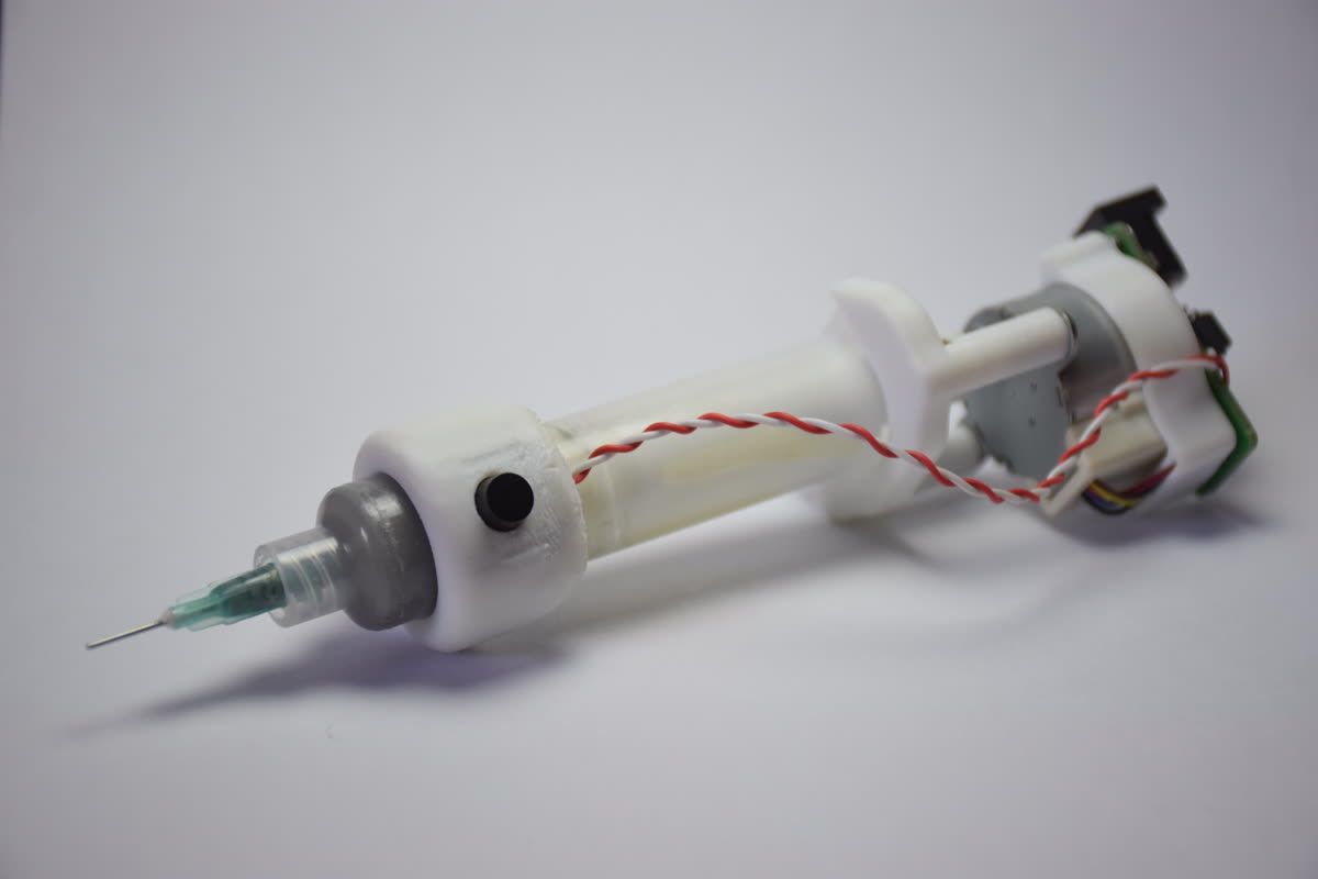 Solder Paste Dispenser
Pressing the button one time dispensed a fixed amount of solder through the nozzle. If the trigger button is left alone for some time, the motor will rotate some steps backward to release the pressure inside. Otherwise, the solder will ooze through the end. I used a screw to convert the rotational motion into linear motion.
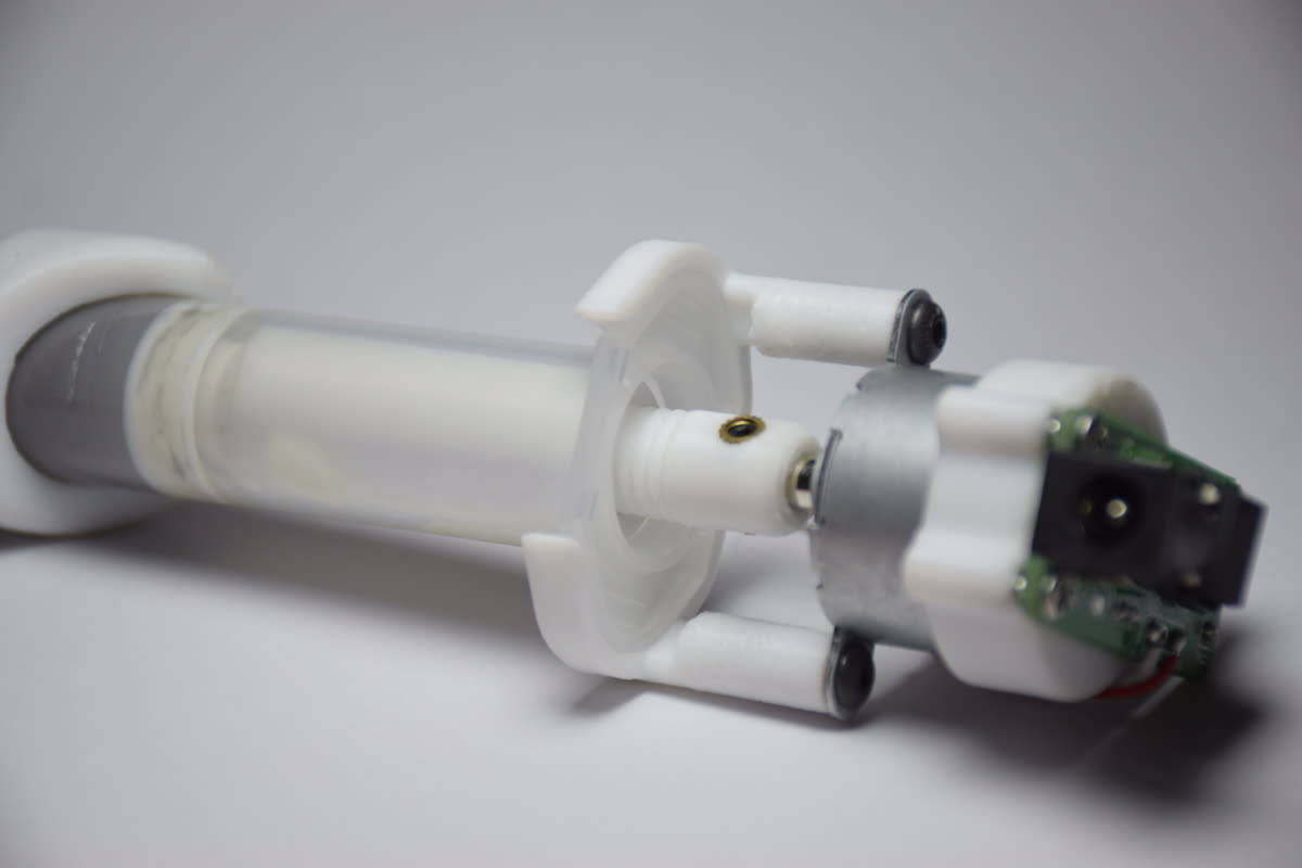 Screw converts the rotational motion of the motor into linear motion
Most of the parts that need to complete the project can be 3D printed. I designed these parts to fit with standard solder paste syringes. To complete this build, other than the 3D printed parts, you’ll need the following list of components.
- 24BYJ-48 5V Stepper Motor; Diameter 24mm
- ATtiny85 Microcontroller; (DIP-8)
- 5V DC power supply
- ULN2003A Stepper driver IC; (SOP-16)
- M3 Screws and insert nuts; Screw(Length=10mm), Insert Nut(Height=3mm, outer diameter=4.2mm )
- 3mm LED
- 5.5mm DC Power Socket
- Two 1k Resistors; (0805)
- Push Button; (12mm-square)
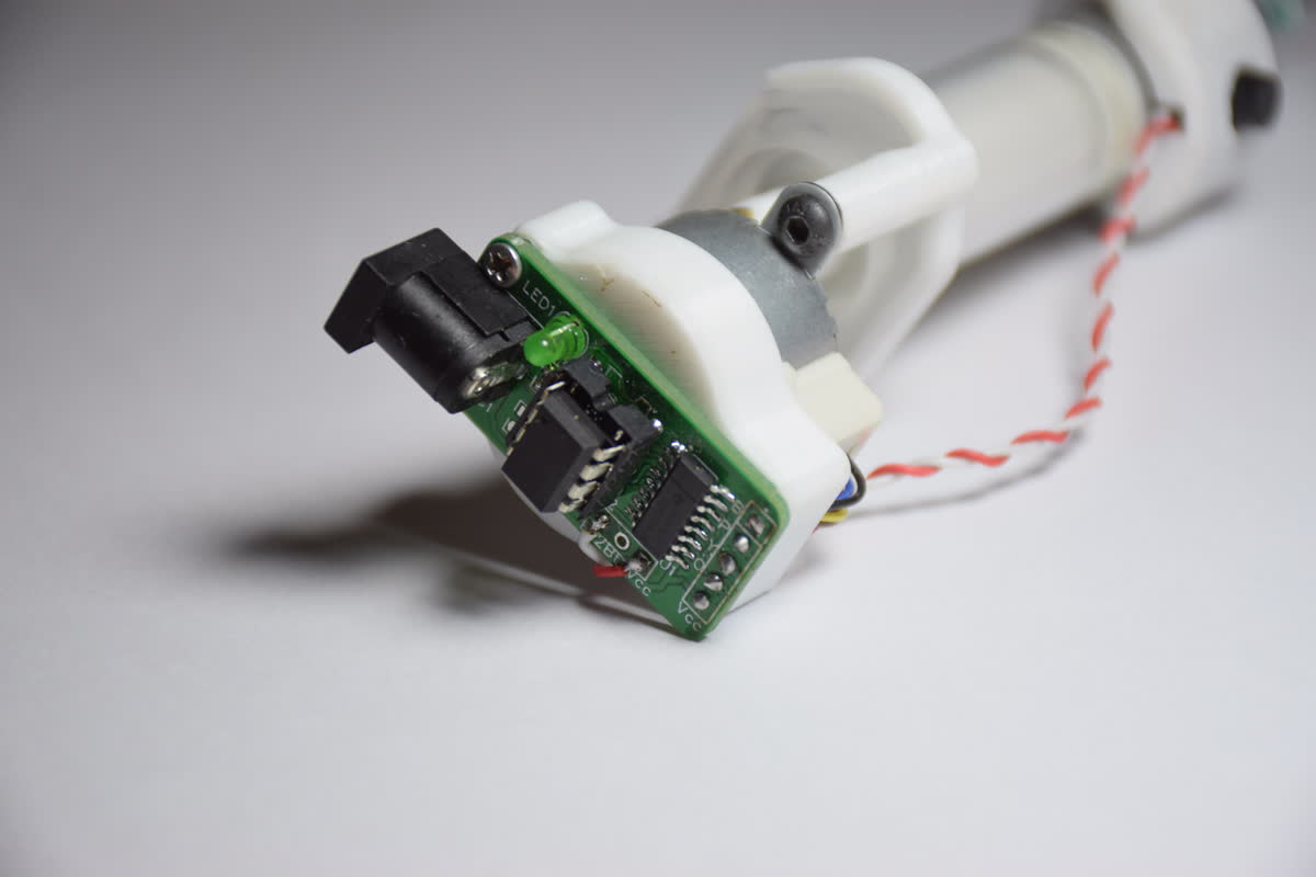 Fully populated custom controller board
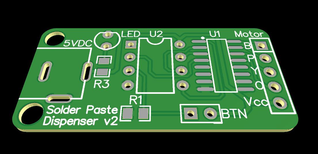 Controller PCB
I used an Attiny85 microcontroller to drive the stepper motor through a ULN2003A Darlington transistor array. Due to the GPIO limitations of ATtiny85, this device only contains one push button. So, I had to use the only button to control the forward motion. Moving the plunger backward to release the pressure is automated with a timer. Although the RESET pin of the microcontroller can be re-purposed as an IO pin with some modification to the ATtiny85 fuses, I went with that push-button because I did not want to overcomplicate the project.
If you want to control the backward motion manually, you can do it in two ways. You can add an extra push button to the RESET pin, or you can change the existing code of this project to rotate the motor backward when a double press register on the push button.
1: Building the PCB
You can build the PCB either by ordering it from a fabrication house or simply DIY. But I think fabrication is the best option because PCB manufacturing is really cheap these days. And also, soldering the SOP-16 package can be quite challenging. You can use an IC base to mount the microcontroller in case you need to update the firmware along the way. You can find the link to the fabrication (Gerber) files and the schematic in the Design files section.
2: Upload the firmware to the Attiny85 (Arduino as ISP method)
The easiest way to upload the firmware into the Attiny85 chip is by using another Arduino as the programmer. (Assuming you already have an Arduino board lying around)
- 2.1: Open Arduino IDE and go to
preferences, then copy and paste the following link in the “Additional Boards Manager URLs:”
https://raw.githubusercontent.com/damellis/attiny/ide-1.6.x-boards-manager/package_damellis_attiny_index.json
 Additional Boards Manager URLs
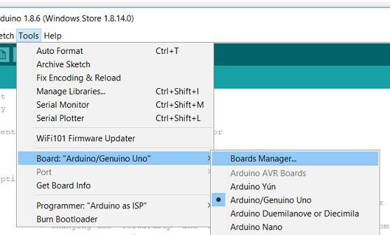
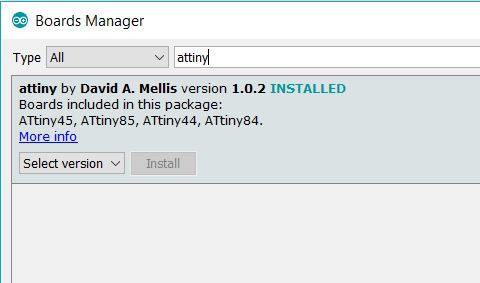
- 2.2: Go to
Tools → Boards → Boards Manager..Then search for “attiny” and install the package containing theATtiny85board.
-
2.3: Open the “ArduinoISP” sketch from the
examplemenu and upload it to an Arduino board. -
2.4: Connect the
ATtiny85and the Arduino board as follows.
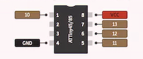
| Arduino -- | -- Attiny85 |
|---|---|
| 10 | 1 |
| 11 | 5 |
| 12 | 6 |
| 13 | 7 |
| 5V | 8 |
| GND | 4 |
-
2.5: Open the firmware SPD.ino with the Arduino IDE.
-
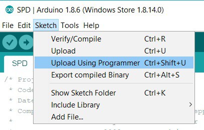
2.6: Go to
Tools → Programmer; choose “Arduino as ISP”. -
2.7: Select “Sketch” in the menu bar and select “Upload Using Programmer”.
3: 3D printing
You can print all the models without supports except the “button ring” model. I recommend printing these parts with 0.1 mm layer height and 100% infill. The models, “screw”, and the “long nut” were designed with very low tolerance to reduce the backlash. So, they might need some light sanding. I used 600 Grit sandpaper for this.
Design Files
You can find all the CAD and Code files for this project on my GitHub page. Also, check out my Thingiverse page and EasyEDA project page. Feel free to change the design files however you like.