Sometimes when we troubleshoot circuits, we have to remove components from the PCB for testing. But if you own an oscilloscope (sadly, I don’t), you could test the parts on the PCB without removing them by using an Octopus Curve Tracer.
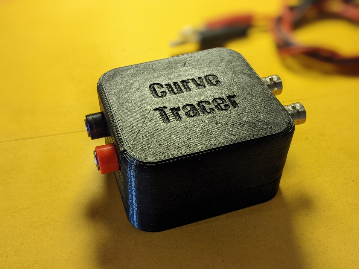 Octopus Curve Tracer
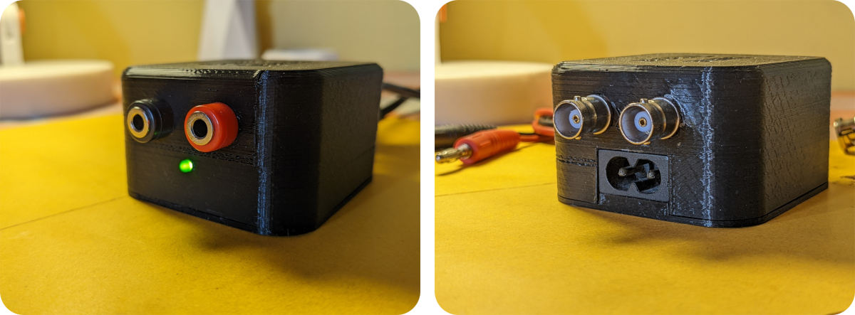 Input and output ports of the device
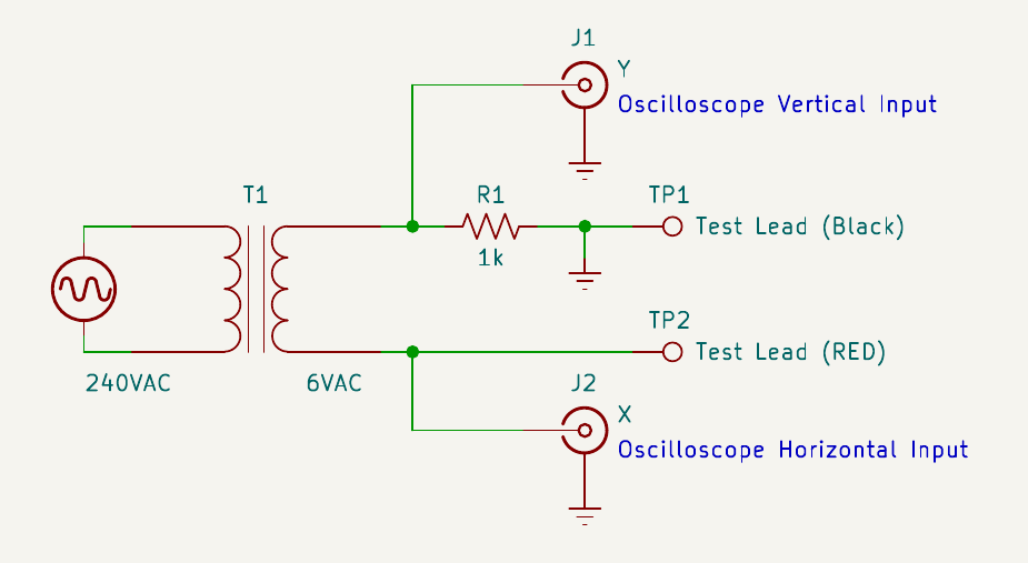
The inside of the device is insanely simple to build. You only need a stepdown transformer and a 1kΩ resistor to limit the current. But as I said before, you will need a two-channel oscilloscope to see the output.
 Schematic
According to the schematic, we need to connect the oscilloscope’s Ch1(X) to J2 and Ch2(Y) to J1. Then we need to put the oscilloscope into the XY-mode. Finally, we place the Device Under Test (DUT) between the test lest leads TP1 and TP2. A transformer is used in this circuit to generate a sweeping voltage across the DUT. I used the following list of parts and components to build this device.
- 1 ×
6VTransformer - 1 ×
1kΩResistor - 2 × BNC Female Connectors
- 2 × Male-Male BNC cables
- 1 × Two pin AC power port and a matching cable
- 2 × Banana ports
- 1 × Green LED
- 1 × 3D Printed enclosure
The theory behind the tester is also quite simple. According to the schematic, the X-axis (horizontal) of the oscilloscope plots the voltage across the DUT. And the Y-axis (vertical) plots the voltage between the R1 resistor. According to Ohm’s Law, we know that the current through a conductor is directly proportional to the voltage across it. Since the resistor R1 was purposefully selected as 1kΩ, we can easily calculate the current by multiplying the voltage with ×10⁻³. Therefore, it essentially plots the voltage between the DUT on X-axis and the current through the DUT on Y-axis. Selecting the appropriate voltage scale on the scope will allow us to observe the I-V curve of the DUT.
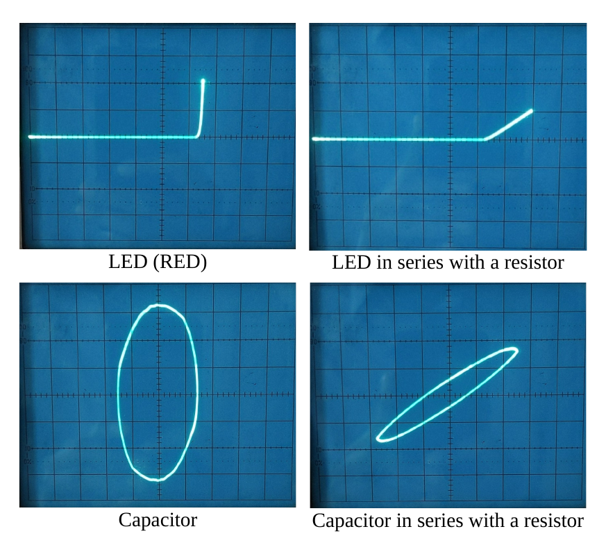
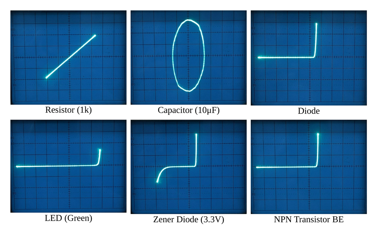 Characteristic curves of basic components
On the above figure, you can see several characteristic graphs of several active and passive components observed from a Cathode Ray Oscilloscope(CRO). One great thing about this tester is that you can observe the I-V curve of components when they are connected together in a circuit.
 IV characteristic after adding a series resistor
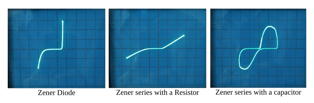 Zener characteristic with a series resistor and a capacitor
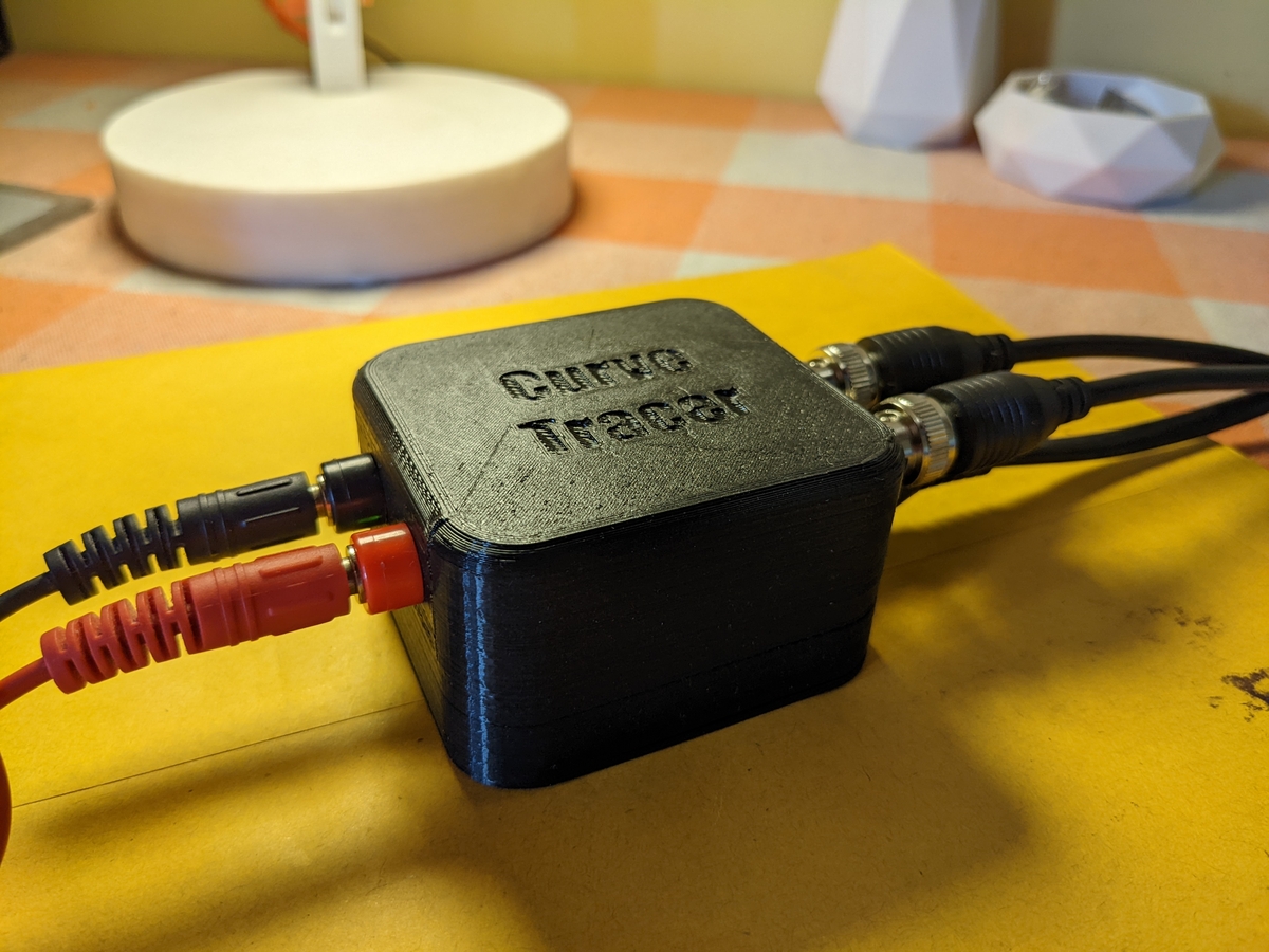 Octopus Curve Tracer with all the cables are connected
Design Files
You can find all the CAD files of this project on my GitHub page.