Nowadays, anyone with a basic understanding of electronics can build their security systems with the help of microcontrollers like Arduino development boards. This project is my take on that.
 Basic module connections
My family owns a small grocery store, and due to several brake-ins in the nearby area, I’ve decided to build this simple security system. As the primary sensor of my build, I decided to use a microwave-based motion detector RCWL-0516.
Since the RCWL-0516 has a limited range, I designed the system in a small room or a small area. If any disturbance is detected while the system is armed, the owner will receive a call, and the alarm will go off.
Basic diagram:
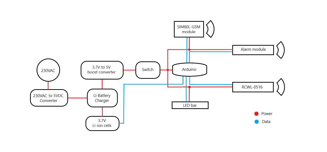
The following diagram illustrates the power and data connections of this project.
 Basic module connections
 Connections of the modules in side the system
Features:
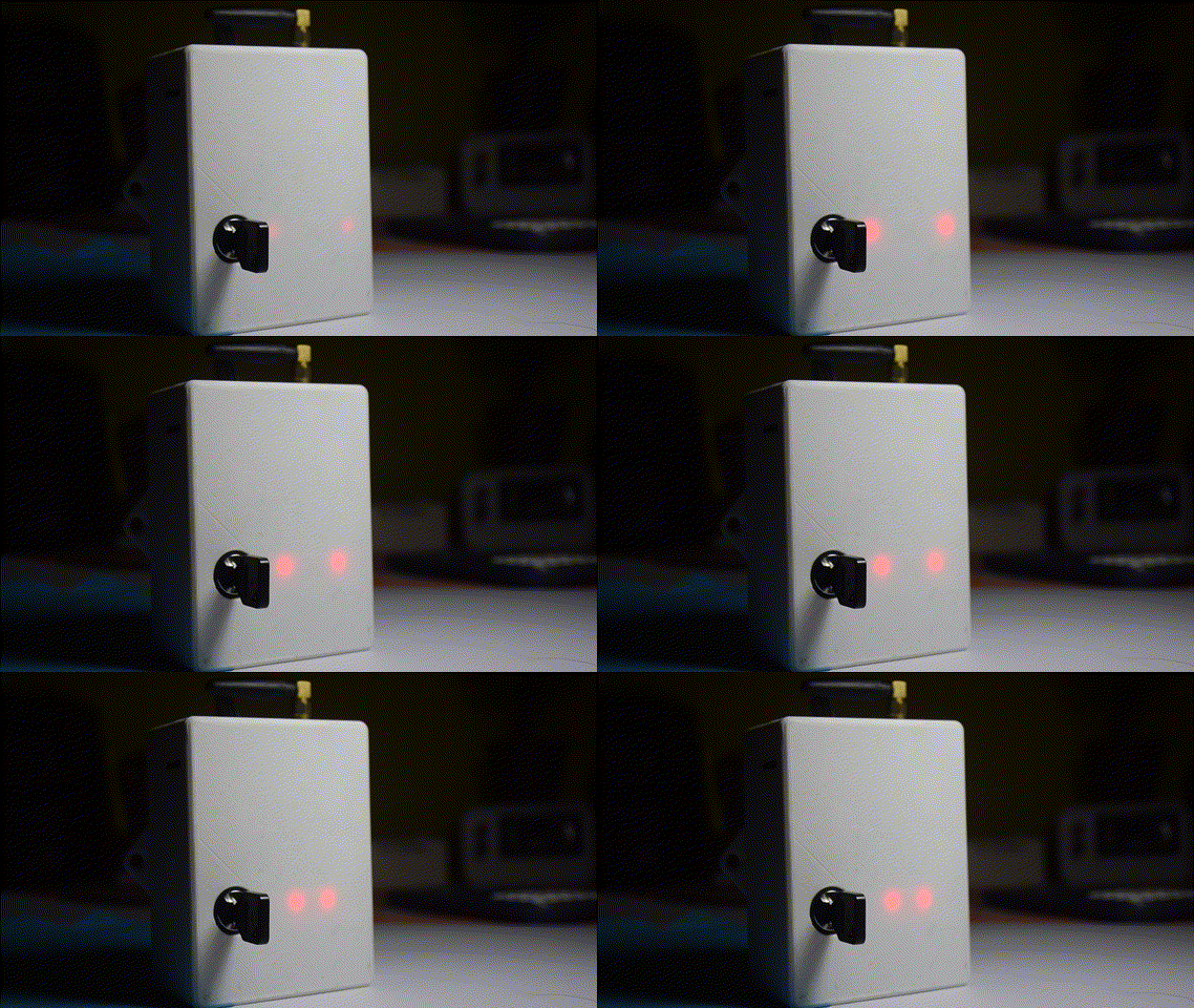
- Only the key can arm or disarm the device
- When the owner turns on the system using the key, there will be a couple of minutes before it armed itself, providing several minutes for the owner to close the shop.
- I’m using a pre-paid package for the sim card in the SIM800L module. Therefore, during the arming sequence, the system will check the available credit balance on the SIM card by USSD code. If the balance is within a critical range, the owner will get SMS notification on his phone. To save credit, when the balance goes below the critical credit range, the owner will not receive any further messages to save the remaining sum.
 UART connection for programming the arduino board if needed
- After the arming sequence, if the system detects any movement, it waits for some predetermined period for the system to be disarmed using the key in case the owner is the one who triggered the system. I added this delay because we do not want to sound the alarm unnecessarily every time the store opens in the morning.
- If the system is not disarmed after the above-mentioned period, the alarm will go off, and the owner will receive a call from the system.
- The system is primarily powered by the mains AC power. In case of a power outage or a deliberate power cut, the system will power itself using backup batteries(
2x18650Li-Ion). - The owner will receive an SMS notification when the backup battery runs out of juice.
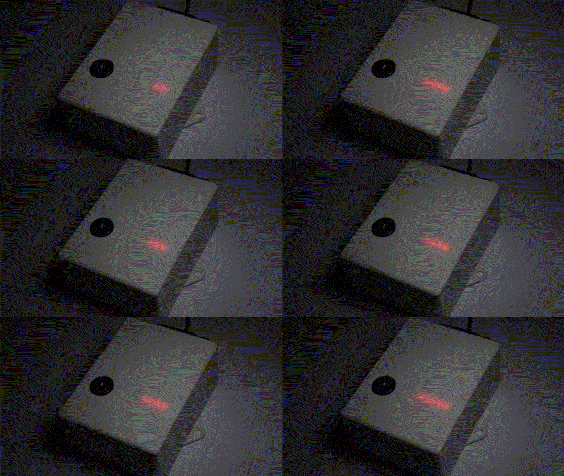
For visual indication, I’ve used a custom-made LED bar consisting of 8 LEDs (0603-SMD)


Parts:
The following list contains the parts I used to build this security system.
- 1 ×
RCWL-0516Microwave radar sensor - 1 ×
SIM800LGSM module - 1 × 3.7V to 5V boost Converter
- 1 × Key operated switch
- 1 × Arduino pro mini 168 (5V-16M)
- 1 × 230VAC to 5VDC AC/DC power converter
- 1 × 18650 Li-ion battery (any 3.7V Li battery)
- 1 ×
TP4056Li Battery Charger and Protection Module - 1 × 5V Piezo Siren Module
- 1 × 3D printed enclosure
- 1 × DIY LED Bar using
8x0603LEDs,8x0805resistors and1xSN74HC595Shift Register
 Component closeup
Design Files
You can find the firmware file for the arduino on my GitHub page.