This wall outlet can turn On/Off any device plugged into it. It uses an ESP8266-01 module to connect to the home network over WiFi.
Recently I wanted to remotely turn on/off a device connected to a wall outlet. Building an RF transmitter and a receiver was an option, but why build two separate RF units when we already have WiFi all around us.
But, instead of integrating WiFi capabilities into the device itself, I’ve decided to build a WiFi controllable wall outlet adapter.
 WiFi Switch
Since I had several of these universal travel adapters lying around, I used them as the reference for my design. Also, I repurposed their internal metal parts and terminals to act as the contact points.
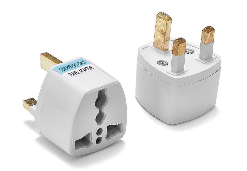 Universal Travel Adapters
 Internal circuitry of the device
The goal of this PCB is to switch the live connection on/off using a relay. Then the relay needs to be controlled by the WiFi module (ESP8266-01). To power the ESP and the relay, I used a Hi-Link 5V power module and, it was able to provide 5V up to 600mA. The 5V input is regulated to 3.3v and fed to the ESP module. Unfortunately, as you can see from the extra wires I had to solder, the first version of the board had some issues.
To build this device, I used the following list of parts and components.
- 1 × WiFi module:
ESP8266-01 - 1 ×
230VACto5VDCconverter:HiLink-HLK-PM01 3W - 1 ×
5VRelay - 1 ×
3.3VRegulator:LM1117-3.3V - 1 × NPN Transistor:
MMBT2222A - 1 × SMD Diode:
1N4007 - 3 × Resistors:
1x10kΩ,2x1kΩ - 2 ×
0805Capacitors:0.1μF,10μF - 2 ×
0603LEDs
Version 2
In the second version of the PCB, I solved most of the problems but, I had to resort to some unconventional power routing to get the live connection from the wall and into the relay and then to the metal connector.
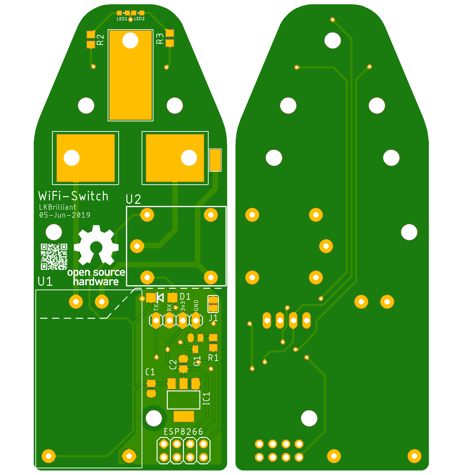 WiFi Switch PCB (v2)
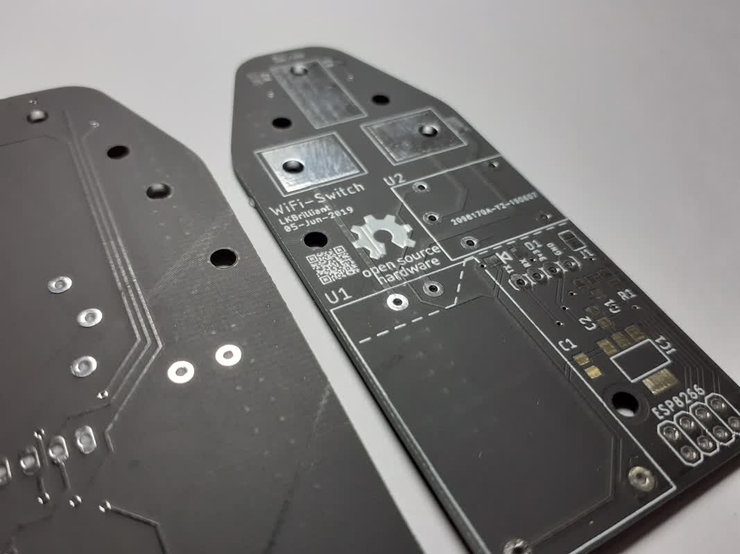 Black Solder masked PCB (v2)
 Power routing contraption
For this to work, first, the plastic spacer needs to go on top of the metal connector. Then the small metal ring needs to be on top of the spacer. Then all of the components can be fixed using the screw. I know that this is not the ideal way to handle the mains voltage, but since this is just a prototype and not a commercial product, I’m going to leave it to the next version.
 Basic module connections
Other than that, I’ve encountered some issues when using the GPIO2 pin of the ESP8266-01 with the relay. When booting up, GPIO2 outputs a small pulse, which then turns on the relay. This behavior somehow interrupted the booting of the ESP module. This issue got resolved by changing the pin to GPIO3.
In this version, the ESP module needs to be hard-coded with the home wifi credentials to be able to connect to it.
After the module establishes the connection, it will generate a page in a static IP address that you can access through any device connected to your home network. Using the button on the page, you can turn On or Off the device.

Version 3 ToDo
- Figure out a better(safer) power routing
- Use Non-Plated Through Holes (NPTH) instead of Plated ones
- Add a WiFi Manager to choose the Access point easily
Design Files
Since the project uses the mains voltage, I would not recommend you build this one unless you know what you are doing.
 Schematic of the WiFi Switch
You can find all the CAD and Code files of this project on my GitHub page. Feel free to change the design files however you like.